
Transformers are devices able to transform the voltage of an electrical supply from one level to another. This is necessary because voltage is normally distributed at a level higher than that used by machinery in industry: higher voltages used in the distribution system reduces energy losses in the distribution lines.
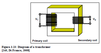
Transformers are static machines made up of a core comprising a number of ferromagnetic plates, with the primary and secondary coils wound around the opposite sides of the core. The transformation rate of the voltages is given by the ratio V2/V1 (see Figure 3.23).
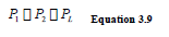
If P1 is the electrical power entering the transformer, P2 the power exiting and PL the losses, then the power balance is:
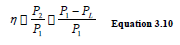
and the transformer efficiency can be written as:
The losses are of two main types: losses in the iron components and losses in copper components. Losses in iron are caused by hysteresis and eddy currents inside ferromagnetic core plates; such losses are proportional to V2 and are from about 0.2 to 0.5 % of nominal power Pn (= P2). Losses in copper are caused by the Joule effect in copper coil; such losses are proportional to I2, and are estimated roughly from 1 to 3 % of nominal power Pn (at 100 % of the load).
Since a transformer works on average with a load factor x lower than 100 %, (Peffective = x Pn), it can be demonstrated that the relationship between the transforming efficiency and the load factor follows the curve in Figure 3.24 (for a 250 kVA transformer). In this case, the transformer has a maximum point at a value of about 40 % of the load factor.
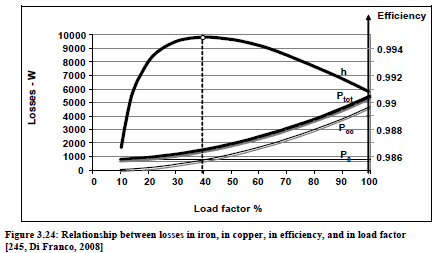
Whatever the power of the transformer is, the relationship between efficiency and load factor always shows a maximum, set normally on average at around 45 % of the nominal load.
Due to this distinctive behaviour, it is possible to evaluate the following options in an electrical power (transformer) substation:
●if the global electric load is lower than 40 - 50 % Pn, it is energy saving to disconnect one or more transformers to load the others closer to the optimal factor
●in the opposite situation (global electric load higher than 75 % Pn), only the installation of additional capacity can be considered
●when repowering or updating the transformer substation, installing low loss transformers, that show a reduction of losses from 20 to 60 % is preferred.
變壓器是一種可以將電源供應電壓升或降壓到所要電壓的裝置。電壓通常都是以高壓輸配方式,這樣可以減少輸送時的線路損失,所以一般輸配電壓都會比使用端要高。
如上圖,變壓器是一靜態裝置,由一疊磁性鐵片做成的磁心,以一次線圈及二次線圈對側環繞而成,其變壓比率為輸入電壓(V1)與輸出電壓(V2)之比值。
如P1是進入變壓器的電力,P2為送出電力,PL是損失,則電力平衡公式為:
P1 = P2 + PL
其效率公式 η=P2 / P1 = (P1-PL) / P1 = 1 –PL / P1
變壓器的損失有兩種型態:鐵件及銅件的損失。鐵件的損失來自磁滯現象和磁鐵心的渦電流,這些損失和電壓的平方成正比,大約是輸出端電力的0.2~0.5%。
銅件的損失來自銅線圈的焦耳效應,其損失與電流的平方成正比,估計損失約為輸出電力在100%負載時的1~3%。
因為變壓器以一低於100%平均負載因素x運作。圖3.24是一250kVA變壓器的變壓效率和負載因素之間的關係圖,在這圖中顯示這變壓器在40%負載因素時有一最高的變壓效率值。
不論變壓器的電力是什麼,其效率值與負載因素之間的關係,正常情況下是在平均在45%負載時有最大值。由於這特性所以在一電力站(變壓站)可以以下列選項:
●如果整體電力負荷低於變壓器輸出電力的40~50%,則可以拆接一個變壓器,或將多個變壓器再接其他負荷,以達到適當的負載因素。
●反向而言,如全體電力負荷高過75%輸出電力,只能考慮增設另外的變壓器。
●當重置或升級一座供電站(變壓站)時,應裝設低損變壓器,這樣可以減少20~60%的損失。
None known.
無資料。
The optimisation criteria are applicable to all transformer rooms. Optimising the loading is estimated to be applicable in 25 % of cases.
The number of new transformer power installed/repowered every year in industry is estimated to be 5 % and low loss transformers can be considered in these new/repowered cases.
優化的一些作法可以應用在變壓器室,最佳化負載估計可以應用在25%的案例。
產業界每年大約有5%的變壓器安裝或更新,在這些案件中可以考慮改用低損變壓器。
In the case of the installation of low loss transformers with respect to ‘ normal series’ transformers, or in substitution of low efficiency transformers operating at present, payback times are normally short, considering that transformers operate for a high number of hours/year.
把低損變壓器當作常態變壓器來新裝,或替換現時使用中的變壓器,而且每年作業時數夠多夠長,則投資回收年限可以縮短。
Energy Efficiency (2009) 3.5.4